|
GERMAN
DEVELOPMENT:
Work
on the gas turbine engine was going on in Germany concurrently with Whittle�s
work in Britain. Serious efforts toward aircraft jet propulsion were started
in the mid 1930s.
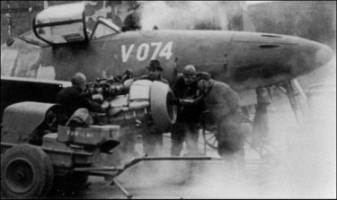 The
main German development took place in 1940, when Willi Messerschmitt produced
the Me 262, a 805 Km/h fighter, powered by two axial-flow engines, the
Jumo 109-004a. More than 1600 Me 262 fighters were built in the closing stages
of World War II, but they reached operational status too late to
challenge the overwhelming air superiority gained by the Allies seriously. The
main German development took place in 1940, when Willi Messerschmitt produced
the Me 262, a 805 Km/h fighter, powered by two axial-flow engines, the
Jumo 109-004a. More than 1600 Me 262 fighters were built in the closing stages
of World War II, but they reached operational status too late to
challenge the overwhelming air superiority gained by the Allies seriously.
TYPICAL
OPERATION:
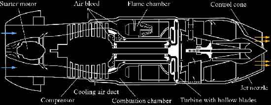
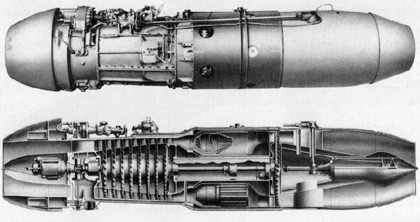
A
gas turbine engine is an internal combustion engine that consists of three main
parts:
The
axial-flow compressor
The
combustor
The
turbine
The
front, or inlet, duct is almost entirely open to permit outside air to enter the
front of the engine. The compressor works on this incoming air and sends it to
the combustion or burner section at high pressures. In the burner section, the
fuel, similar to kerosene, is sprayed and mixed with the compressor air. The
mixture is then ignited by devices similar to spark plugs. Extremely hot gas
streams from the combustor and escapes through the blades of the turbine,
spinning them at high speed. The turbine extracts most of the energy from the
gas stream and uses this energy to turn the compressor and the accessories.
After
leaving the turbine, there is still enough pressure left to force the hot gases
through the exhaust duct and jet nozzle at the rear of the engine at very high
speed.
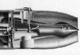
AXIAL-FLOW
COMPRESSOR ENGINES:
 The
Me 262 fighter used an axial-flow compressor engine, chosen because of its
ability to handle large volumes of airflow. Unfortunately, it is more
susceptible to external-object damage, it is expensive to manufacture and it is very
heavy in comparison with the centrifugal compressor with the same compression
ratio. The
Me 262 fighter used an axial-flow compressor engine, chosen because of its
ability to handle large volumes of airflow. Unfortunately, it is more
susceptible to external-object damage, it is expensive to manufacture and it is very
heavy in comparison with the centrifugal compressor with the same compression
ratio.
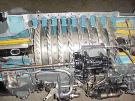
The
axial-flow compressor is made up of a series of rotating airfoils called rotor
blades, which are made up of an alloy of stainless steel containing Nickel (30%)
and Chromium (15%), and a stationary set of airfoils called stator vanes made up
of a particular steel alloy containing Chromium and Manganese. A stage is a row
of rotating and stationary blades. The entire compressor is made up of a series
of alternating rotor and stator vane stages.
As
its name implies, the air is being compressed in a direction parallel to the
axis of the engine.
This
axial compressor has the advantage of being capable of very high compression
ratios with relatively high efficiency with respect to the British centrifugal
compressor engines developed in the same years.
COMBUSTION
CHAMBER:
In
the Jumo 109-004A/B/C/D engines there are six combustion chambers located around
the structure.
The
combustion chamber is able to move axially as a consequence of the thermic
dilatation that happens during ignition.
The
first stage consists in the separation of the primary and secondary
air as shown in the figure:
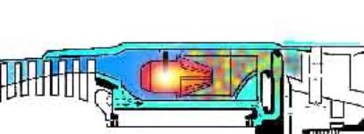
Then
the fuel is forced to go out against the stream, is mixed with the primary air
and ignited. A bulkhead prevents the combustion chamber from being subject to
the high
temperatures caused by the hot exhaust gases. After they have passed through the chamber, the secondary air is
added to them to prevent the overheating of the turbine.
TURBINE
CONSTRUCION:
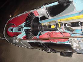 The
turbine wheel is one of the most highly stressed parts of the Jumo 109-004. The
turbine assembly is made up of two main parts, the disk and the blades. The disk or
wheel is a statically and dynamically balanced unit of specially alloyed steel
containing mainly Chromium, Vanadium but also Manganese, Magnesium, Silicon, and
Carbon. The
turbine wheel is one of the most highly stressed parts of the Jumo 109-004. The
turbine assembly is made up of two main parts, the disk and the blades. The disk or
wheel is a statically and dynamically balanced unit of specially alloyed steel
containing mainly Chromium, Vanadium but also Manganese, Magnesium, Silicon, and
Carbon.
The
blades are attached to the disk by means of gudgeon pins designed to allow for
different rates of expansion
between the disk and the blade while still holding the blade firmly against
centrifugal loads.
The
61 blades of the Jumo turbine engine are made up of stainless steel containing
mainly Nickel and Chromium (0.15%C; 0.7%Si; 0.6%Mn; 1.7%Ti; 30%Ni; 19%Cr). The
buckets are empty inside and supported by an air cooling system.
JET
NOZZLE:
 The
nozzle of the Jumo 109-004 is variable, so as to maintain sufficient efficiency at low
speed. In the part near to the engine there is a device that can move along the
structure of the engine for 0.20 meters, restricting the section of the nozzle.
By doing that, the pilot can also control the temperature of the exhaust
gases. The
nozzle of the Jumo 109-004 is variable, so as to maintain sufficient efficiency at low
speed. In the part near to the engine there is a device that can move along the
structure of the engine for 0.20 meters, restricting the section of the nozzle.
By doing that, the pilot can also control the temperature of the exhaust
gases.
|